》》PART1
Generally, the polarity sign of power factor represents the phase relationship between voltage and current. To illustrate this, the following will use the grid and micro-inverter as examples.
Grid
In the grid, the current charges direction periodically, and the voltage also periodically reverses because the current changes direction. The value of power factor is different based on the phase difference between voltage and current.
Current in Phase with the Voltage
When the voltage and current are in the same phase, both the current and voltage curves peak, and reach zero at the same time. In this case, the phase angle between the voltage and current is zero, meaning there is no reactive power flow in the circuit. Thus, the value of power factor is one.
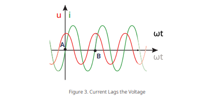
Current Lags the Voltage
When the current lags voltage in an ac circuit, in the interval [A, B], the current curve encounters the zero crossings of the time axis after the voltage curve. Thereby giving rise to a lagging power factor, and the value of power factor lies between 0 and 1.
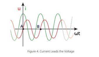
Current Leads the Voltage
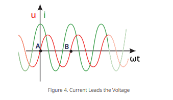
When the current leads voltage in an ac circuit, in the interval [A, B], the current curve encounters the zero crossings of the time axis earlier than that of voltage curve. This is called leading power factor, and the value of power factor lies between -1 and 0.
》》PART2
For micro-inverter
When it comes to the micro-inverter, the polarity sign of power factor also represents the phase relationship between voltage and current. But, a more straightforward interpretation of the polarity sign of power factor is that the polarity represents the direction in which reactive power is transferred.
We define that the reactive power is absorbed when the power factor is negative, whereas the reactive power is generated when the power factor is positive.
Adjusting the value of power factor can control the active power output and reactive power output. To illustrate it, this chapter provides an example. Here, we can take ESTAR ENERGY as an example, and the following are some technical data of ES-2000:

Among the parameters, the default power factor is greater than 0.99, indicating the apparent power is almost equal to the active power rating (W). In this case, all of the power is delivered and dissipated in the load. If the micro-inverter operates using the default 0.99 power factor setting, then,

If the micro-inverter operates using the o.8 power factor setting, then

From above, it is easy to see that a larger value for power factor, leads to an increase in reactive power, which ultimately results in a decrease of active power.
What does a power factor of -0.8 mean and why is it negative?
To begin with, we need to address that the sign just indicates the leading and lagging nature of the power factor. In this example, the negative (-) sign before 0.8 means the current phase leads the voltage phase. And the number 0.8 means that, out of 100%, the system is consuming 80% active power. For example, if the power factor is 0.8 and the nominal output power is 2 kVA at this case, then the active power is 1.6 kW, while the reactive power is 1.2 k Var ( ![]() )
)
Generally, when the power factor of micro-inverter is 0.8, the micro-inverter generates active and reactive power to the system, to meet the needs of the power grid for reactive power; If the power factor becomes -0.8, the micro-inverter absorbs reactive power.
To put it in a nutshell, when the power factor is negative, the micro-inverter absorbs reactive power; when the power factor is positive, the micro-inverter generates reactive power.
》》PART3
How to enabling the Power Adjustment Function by ESTAR ENERGY
There are two ways to adjust the value of power factor(for plant), active power output and reactive power output through ESTAR ENERGY Cloud Monitoring platform(https://monitor.estarpower.com/platform)or ESTAR PRO APP.

Figure 1 Power Adjustment
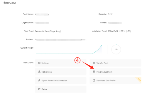
Figure 2 Power Adjustment

Figure 3 Power Adjustment
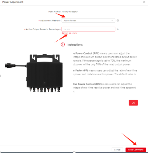
Figure 4 Power Adjustment
》》PART4
Conclusion
This document discusses how apparent power, active power, and reactive power relate, and how the power factor can be adjusted to control the amount of active and reactive power output. To summarize, when the microinverter is not requested for the reactive power, it will generate power using the default power factor setting. If the reactive power generation is required, users can adjust the power factor through ESTAR ENERGY Cloud Monitoring Platform according to the grid requirements or their own energy needs.

.jpg)